Hardware
The main controller of this board is RP2040. The ESP32-C3-MINI-1-N4 is placed for Wi-Fi and BLE connection. However in order to utilize the remaining pins, they have been routed to the header.
ESP32-C3-MINI-1-N4 contains 4MB Flash.
Connection
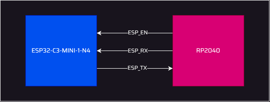
We have selected UART connection between RP2040 and ESP32C3. We will use AT commands over UART.
There might be alternative command protocols than AT, however it will require some effort. Therefore at the moment we will go with AT commands.
The connection diagram can be seen below.
ESP32-C3 doesn't support AT commands over SPI by default.
| ESP32-C3 | RP2040 |
|---|---|
| ESP_EN | GPIO21 |
| ESP_RX | GPIO16 |
| ESP_TX | GPIO17 |
More info about UART AT for ESP32C3
Software
The ESP32-C3 module serves as a dedicated co-processor for connectivity on this development board. A pre-built firmware, designed to function seamlessly with AT commands through the UART interface, has been developed and released by Espressif.
This ESP-AT firmware has already been installed to our boards during production, so you can readily use the connectivity features of our development board without any extra effort. However, if you wish to reprogram the ESP32-C3, please follow the instructions provided below.
ESP-AT Firmware Installation (Optional)
As mentioned, the installation of ESP-AT firmware onto the ESP32-C3 module is entirely optional.
In order to program ESP32-C3, please follow the instructions provided in the Downloading guide for ESP32C3.
Hardware Connections
To proceed, kindly follow these two steps prior to software installation:
- Begin by short-circuiting the JP2 jumper located on the development board.
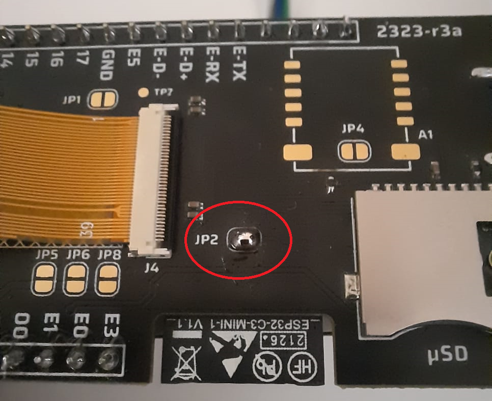
Please remember to desolder and disconnect the JP2 jumper after the installation is complete. Failing to do so may result in improper operation of the ESP32-C3 module.
- Utilize USB connections to the dedicated pins. Ensure that these four connections are properly established:
- VBUS
- D+
- D-
- GND
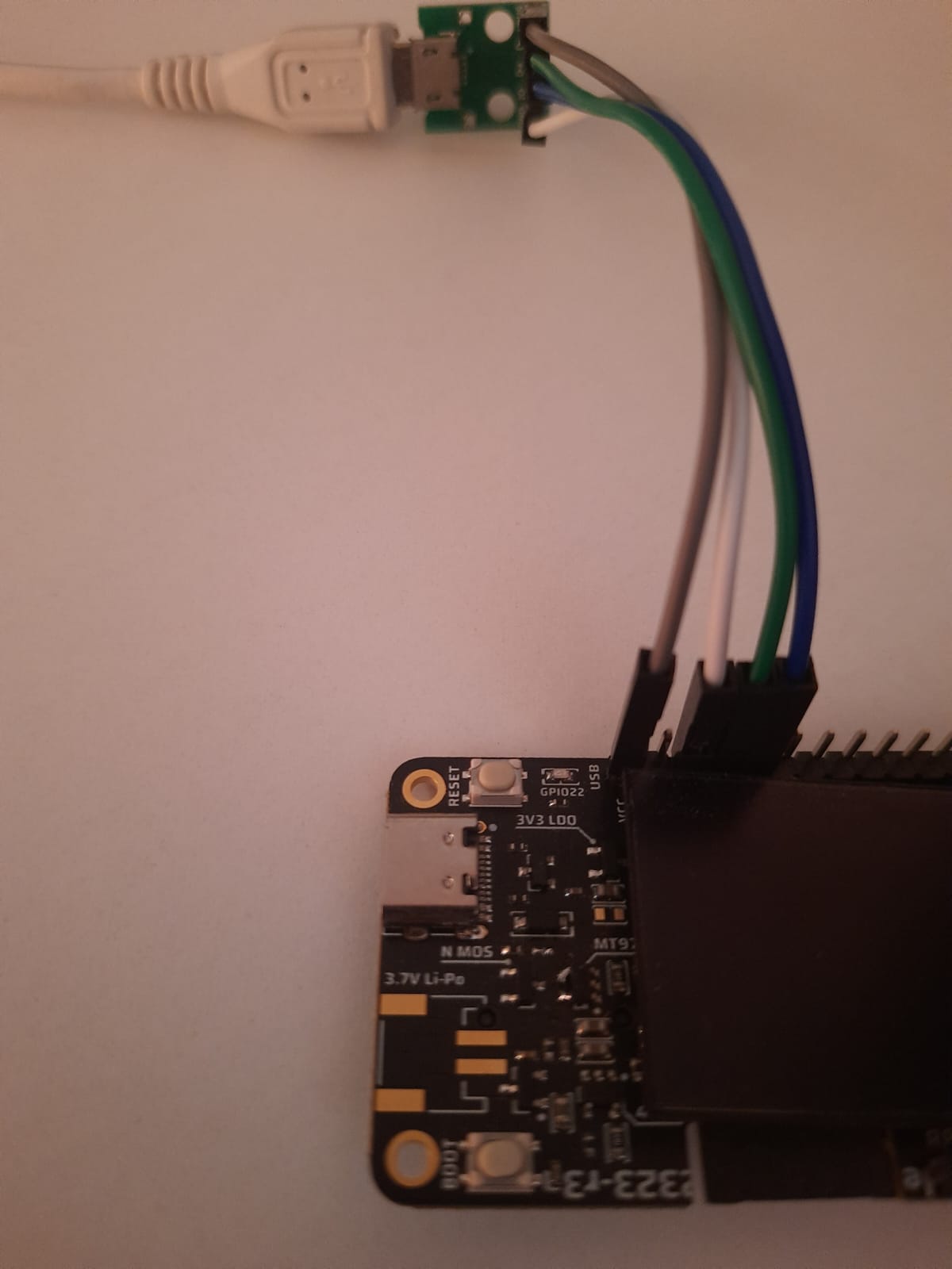
You can find the compatible USB breakout board part from this link
Once these steps are accomplished, you can proceed with the firmware installation process.
Firmware Installation
To install the firmware onto the ESP32-C3 module, please download both the Flash Download Tool and the AT Firmware using the provided links below:
ESP32-C3-MINI-1-AT-V2.4.2.0.zip
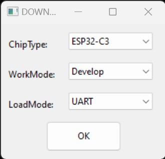
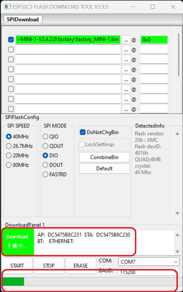
Once you have extracted the downloaded Flash Download Tool, kindly launch the application. Within the tool, opt for "ESP32-C3" as the designated chip type, and then proceed by selecting the "OK" button.
Subsequently, the programmer interface will become visible. Prior to commencing the installation process, kindly execute the provided steps:
- Navigate through the file explorer and select the "factory_MINI-1.bin" file.
- Mark the checkbox adjacent to the file path to confirm your selection.
- Input "0x00" as the starting address.
- Confirm that the "DoNotChgBin" property is selected.
- Check the physical USB connection to ensure it is correctly established.

Proceed by pressing the "Start" button in order to initiate the installation process. Please take into account that related information will be displayed on the download panel, and the progress bar will be in operation throughout the procedure.
Following the completion of the installation process, you should observe the "Finish" statement displayed against a blue background, as illustrated below:
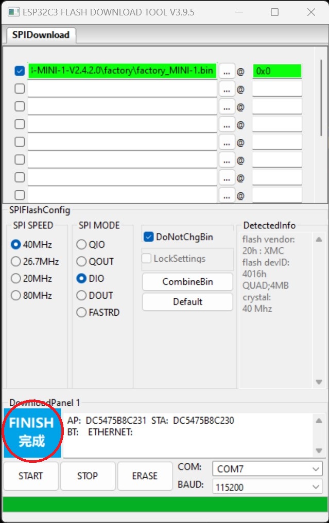
You can directly close the Downloader program after the installation and then proceed to test the connectivity by using our sample WiFiConnection code.
In our demo code, the development board initiates communication with the ESP32-C3 module through five AT commands, configuring the SSID as "AlpElectronix" and the password as "12345678". When you run our WiFi demo code, you can expect to observe the screen depicted below:

Feel free to customize the example code with your preferred SSID and password to give it a test run.
char commands[TOTALCOMMANDS][100] = {
    "AT\r\n",
    "AT+RESTORE\r\n",
    "AT+CWMODE=1\r\n",
    "AT+CWJAP=\"AlpElectronix\",\"12345678\"\r\n",
    "AT\r\n"};
Support
In the event that you require technical support, you can reach out to us by sending an email to contact@alpelectronix.com. Our team is dedicated to providing prompt and effective assistance to help you resolve any technical issues you may encounter while using our products. Don't hesitate to reach out to us if you need assistance or have any questions about our products.